
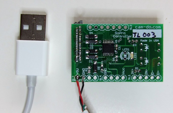
Timer Controller
The Cam-Do Timer Controller is normally used to take time lapse photographs but it can also control the times the camera is off and on based on an external trigger input on the board which can be operated by any device which can provide a DC trigger signal of 3V to 15V.
This allows for a great deal of flexibility in operating the camera using intervalometers, timers, motion detectors, security devices, thermostats, trip wires, computer control, and many other devices.
If you are connecting an external trigger to the controller board, you will find the 0010 test mode useful for testing your circuit.

Cam-Do Controller Board Pinouts
| USB Power | Input for 5.0V to charge the Hero 2 battery |
| LED | +3 V output when camera is on suitable for driving LED |
| GND/Vcc | +3-4 V power (Hero 2 only) Can be used with switch type triggers. |
| IN+/IN- | 3-15 V external trigger input |
| O+/O- | Max 35V @ 50mA NPN OC output |
Note: some earlier boards sold as timer controls only, do not have the opto-isolators in place, so they need to be added to use the input or output connections. The correct part is the LTV-817 and it is mounted on the back of the PC board (the side with the dip switch). The current firmware includes the input trigger function and output switch functions. Older boards may have firmware with only the input trigger.
The 5.0 V USB charging voltage cannot be applied to Hero 3 Cameras via the Herobus connector. This option is for Hero 2 cameras only.

MD-002 Controller Board Pinouts
The MD-002 Motion Detector Controller Board has the same features as the TL-002 Time Lapse controller board with the addition of an on-board power supply with a 5 volt regulator which can be used to power accessories off the camera battery.
Trigger Input Testing
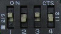
0010 If the switches are set to off-off-on-off, the controller will enter a test mode. The green LED on the controller card will come on when the trigger signal is detected. This is handy for testing the connections and your signal source without triggering the camera.
The HD Hero must be ON to use this test. With the Hero 2 it doesn't matter if the camera is on or off.
Trigger Input Operation
Regardless of the signal source, the setting required for the controller board to respond to an external trigger signal is 0110. When the trigger input is detected, the camera will turn on and remain on while the trigger signal is present.
After the trigger signal disappears, the camera will remain on for the shoot time as programmed using the instruction in the Time Controller Manual. The 1010 reset command is the quick way to unprogram any previously programmed delays.
The Hero 3 Black version of the GoPro camera will remain on the for the time programmed using the Super One Button Mode Scripts.
If the trigger occurs again during the shoot time, the timer will be reset to zero, so the camera will remain on for the length of the shoot time after the last trigger signal.
0110.
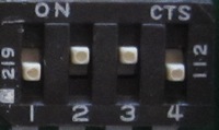 Set the switches on the back of the controller card to off-on-on-off to operate the controller
in external trigger mode.
Set the switches on the back of the controller card to off-on-on-off to operate the controller
in external trigger mode.
Connect your external signal source.
Turn off the camera.
Plug the board into back of the camera.
The camera may come on as you plug in the board. This is normal. Allow the controller to turn the camera off.
Time Lapse Controlled by Enable Signal
This feature is only available on boards shipped after July 1, 2012.
Enable mode operates the camera in time lapse mode only when the enable signal is present. The signal is connected to the IN+ and IN- pads on the board and can be from 3 to 15 volts. Higher voltages just require a series resistor.
A popular request is a time lapse capture which only occurs during certain hours on certain days. This can be accomplished very easily using the controller board input to enable and disable Time Lapse operation using a timer.
A cheap lamp timer can be used to program the hours of operation. The timer can
be a simple mechanical timer or a complicated timer with battery backup and LCD display.
Consumer timers can be bought locally or ordered online
from ebay
or
from Amazon
at low prices and are usually very reliable.

Plug a charger or DC adapter into the timer. The output can be anywhere from 3 volts to 15 volts. You probably have one lying around from a device you no longer use. USB chargers are ideal, but the type is not critical. It must have DC output.
Connect the positive output to the IN+ pad. Connect the negative output to the IN- pad. Test your connections and the timer operation using the 0010 test setting with the board plugged into the camera (turned on for HD Hero).

To use enable mode, set the dipswitches on the board to 1110 (on-on-on-off) or 0111 if you have an older version of the board. Plug the board into the back of the camera. (Note: the dipswitch settings have changed from earlier versions of the board - check the manual appropriate to your board version).
The board will now control the camera in time lapse mode using the settings you have programmed, or the factory defaults. The camera will not turn on unless the enable signal is present from the timer controlled DC adapter. In other words, the camera will only take shots when the timer is on.
If you would prefer to purchase the controller board with a USB Timer Enable cable installed, please contact us for current pricing. We will soon be offering a battery operated timer adapted for use with the controller board. It should be available in August.
Simple Trigger

The simplest system for triggering the control board is a power source and a switch. The power source can be any battery or power supply from 3 volts to 15 volts. This circuit is isolated from the camera by the opto-isolator on the cam-do controller board.
This circuit and the one below have been used to interface the GoPro camera to an intervalometer for complex timing sequences.
One of our earliest custom projects was to use this circuit in racing cars. When the ignition is turned on, the camera records. When the ignition is off, the camera stops recording. The same principle can be applied as a dashboard camera or dashcam.
This circuit is also the basis for the motion detector interface.
Using the Hero 2 Battery as a Power Source

The GoPro HD Hero 2 camera provides a battery source on the bus connector which is available for powering the cam-do board trigger input without the need for external power. The output voltage will vary with the state of the battery from 2.9V to about 4V. The older HD Hero provides only a minimum power source and may work, so we do not recommend using it as it may not operate the trigger reliably, particularly when the battery is not fully charged.
The advantage of using the on-board power is the simplicity of not needing an external battery. This is useful for a simple interface to a push button, or an intervalometer on a short cable, for example.
The disadvantage of taking the power from the camera is that the safety protection of the opto-isolation is lost. It should not be used when long cables are involved which may pick up stray electric fields or static electric shocks.
Connecting an Intervalometer to the Controller
 An intervalometer can be connected to the controller
using either of the circuits above to operate the GoPro camera.
An intervalometer can be connected to the controller
using either of the circuits above to operate the GoPro camera.
If you are using the intervalometer with the HD Hero, use the circuit that includes a battery.
If you have the GoPro HD Hero 2 camera, use the second circuit that is powered by the camera battery.
The exact circuit will depend on the intervalometer you have and what camera it was originally designed to operate. Normally, the shutter control wire will require positive voltage on it for correct switching.
Cam-Do's Programmable Scheduler combines the functions of an intervalometer and scheduler.
Details of the remote shutter pin connections for many cameras can be found by googling. One source showing diagrams for several cameras is doc-diy.net.
Connecting an R/C Receiver to the Controller
If you want to turn the GoPro camera on and off using an extra output from a radio control receiver, it is necessary to decode the RC pulse width modulated signal to a control voltage usable by the controller board. This is easily done using the inexpensive Pololu RC Switch with Digital Output.

The red connection (VRC) to the R/C receiver is optional. Power (minimum 2.0 V, maximum 5.5 volts) must be supplied to the Pololu board Vcc and ground for it to operate. This can be provided by the battery or power supply operating the receiver or other parts of your system or taken from the Vcc and GND connections on the cam-do board which is supplied by the camera battery (Hero 2 models only).

The Pololu board will output a positive signal when the pulse width exceeds 1.6 mSec. This will trigger the cam-do controller to begin shooting video or stills if it is configured in trigger mode, or enable it to take time lapse photos if it is configured in enable mode.
Connecting a PIR Motion Detector to the Controller

A passive infra-red motion detector with a positive output upon detecting motion can be connected directly to the control input of the controller board.
If your motion detector is a contact type, then it looks like a switch and you need to add a battery or other power source to the circuit.
PIR detectors that run off 5 volts can be powered by a USB power supply, which can also be used to keep the camera battery charged for long term permanent operation.
Connecting an X-Band Motion Detector to the Controller

An X-Band microwave motion detector with a positive output upon detecting motion can be connected directly to the control input of the controller board.
The Parallax X-Band Motion Detector can be used with the GoPro camera by interfacing it with the trigger input connection. The X-Band detector is less prone to false positive triggers than the PIR detector. This detector works through glass and plastic, so it is easy to configure a waterproof enclosure encompassing the camera and the detector or to use when mounting the camera and detector by a window. As it does not rely on the moving object being warm, it can also be used to detect inanimate objects or animals that don't radiate infra-red energy, such as reptiles.
The same USB power supply can be used to power the GoPro camera (Hero 2 only) and the motion detector for a permanent installation. Because the Motion Detector uses only 8 mA in standby, it is ideal for solar powered applications in remote areas.
The 5 volt connection to the cam-do controller board extends the camera battery life indefinitely but it is optional and only for the Hero 2. (See below). The 5 volt connection to the Parallax X-Band Motion Detector board is necessary to power the detector.
The simple interface shown using the standard controller software works quite well. The sensitivity adjustment on the detector can be used to vary the range from 2.5 to 10 meters. The output from the detector contains more information about the motion which could be used with custom software on the controller board for more sophisticated detection and discrimination. Contact us for further details if this is of interest to you.
Our MD-003 Motion Detector also includes a power supply on the board to power the detector and requires no soldering to set up. It is available with either the X-Band or PIR sensor.
Using a Photocell with the Motion Detectors
 The addition of a photocell in line with the motion detector allows for daylight operation only.
The example uses the WAITRONY KE-10720, which costs about 25 cents and has a resistance of less than 1K in a daylight and over 500K in the dark. Similar cells are available anywhere electronics parts are sold.
The photocell is inserted between the sensor output and the controller input. Obviously, the photocell needs to be in a position where it will be exposed to the ambient light. Clear silicone can be spread over the photocell if it needs to be waterproofed.

Cut the (usually white) wire in the cable between the sensor output and the controller input. Connect the photocell to the end of a cable long enough to reach the position where the photocell will be installed.
This method will work with either the PIR or the X-Band motion detectors.
Connecting Multiple Sensors

Any sensor that produces an output of 3 volts to 15 volts can be connected to the input pins. The diode isolates the sensors from each other, so they do not have to be matched in any way.
If the leads to the sensors are long, and the sensors have an open output when not firing, the resistor prevents noise on the cables from firing the controller input by holding it low.
A good application of this circuit would be a situation where you are trying to get a photo of wildlife. Motion sensors could be mounted near the bait, pointed in a different direction from the camera and a proximity sensor or trip wire can be mounted near the bait. If any one sensor fires, the camera would begin shooting.
Connecting a Proximity Detector to the Controller

The Sharp GP2Y0A21YK and similar proximity detectors can be used with the GoPro camera by interfacing it with the trigger/enable input connection. Optionally, the same 5V can be used to charge the Hero 2 camera battery (5V and GND at the lower-left corner of the board).
A proximity detector is triggered when an object is within a certain range of the detector. It works by bouncing an infra-red beam off the object and measuring the distance. Unlike motion detectors, the proximity detector signals the presence of the object and not its motion. This makes it very useful for monitoring birds on a nest, or animals attracted to a bait trap. The detector can be set in a location some distance from the camera.
The same USB power supply can be used to power the GoPro camera (Hero 2 only) and the detector for a permanent installation.
The 5 volt connection to the cam-do controller board extends the camera battery life indefinitely but it is optional (see below). The 5 volt connection to the Proximity Detector unit is necessary to power the detector.

 The simple interface shown using the standard controller software works quite well.
The trigger distance will depend on the selected detector. In the default mode, the Sharp GP2Y0A21YK (Spec Sheet [pdf]) reliably detected objects at about 15cm(6"), as shown in the graph to the left.
The longer range GP20A02YK (Spec Sheet [pdf]) detector is useful to 150cm (5 feet). Using the default configuration of the controller in digital mode the camera triggers at around 25cm (11") as shown by the red colored region.
The output from the detector contains more information about the distance and motion which could be used with custom software on the controller board for more sophisticated detection and discrimination. Contact us for further details if this is of interest to you.
We can also supply these units wired and ready to use with custom length cables. Contact cam-do.com for current pricing if you are interested in purchasing one or more.
If you have the Motion Detector controller board with a 5V output for powering the motion detector, the 3 pin connector can be used to power the proximity detector, but it is necessary to add a 500 uF 6V capacitor. [image coming]
Triggering with an Accelerometer
An accelerometer can be used to trigger the GoPro camera based on a minimum threshold of motion. For example, the camera can be set up in advance and will automatically begin taking photos when a bike moves, or when a helmet is put on. Or, it can be attached to an animal so it will only take photos when the animal is in motion.
Sparkfun's Wake on Shake module is very easy to interface. Power can be taken from the controller board and the output is compatible with the opto-isolated trigger input on the Cam-Do board.

The accelerometer interface was implemented for Hugh McGregor of the Australian Wildlife Conservancy as a means of photographing feral cats as they pounced on their prey. The tutorial can be found here.
Accessory Output Operation
This feature is only available on boards shipped after July 1, 2012. However, the LED output powered by the camera can be used in a similar way, without the benefit of the isolation, or the ability to customize the firmware for special applications. The H3B board for the Hero 3 Black cameras has additional features shown below.
The controller board is equipped with an opto-isolated output that can be turned on when the camera is on. Details of the interface are in the LTV-817 Datasheets. The NPN transistor can be used to switch low power devices directly, or can be used to switch a solid state relay, such as the SSR25, to turn on lighting systems powered by 120 or 240 volts AC.

Using an N-Channel MOSFET, it is possible to turn on LED lighting or control similar 12-24 volt loads. The Sparkfun MOSFET Power Control Kit ($3.95) is one of many simple boards with a RFP30N06LE MOSFET capable of switching 60 V at 30 A (with a heatsink). + and - below are the appropriate voltage to power the LED light you are using.
Example of using a MOSFET to control an LED light
By default, the output control is disabled to save power. To enable the output control, set the dip switches to 1011 (on-off-on-on). Turn on the camera. Plug the controller board into the back of the camera. The green LED will flash slowly twice, then quickly 3 times, and then go solid as the camera is turned off. Remove the board from the camera and reset the switches to 1111. Output operation will be enabled until it is disabled by a 1010 reset.
To disable the output control, use the 1010 factory reset option to reset all the controller board settings to their default values.
For the Hero 3 Black controller boards there are additional functions available. Use the 1011 setting to toggle through multiple options. Each time the board is plugged in, the LED will flash in a way to convey which output function is enabled.
- 0 flashes then solid. Output is disabled. Default after factory reset.
- 2 flashes then solid. Output is on when camera is on.
- 4 flashes then solid. Output is on when camera is off.
Immediately change the setting back to 1111 or the next time you plug the card into the camera it will move to the next function and you will have to plug it in twice more to get back where you were.
Snubber or Flyback Diodes for Relays. If you connect a mechanical relay to the controller output, do not forget to include a snubber or flyback diode across the relay in the circuit. Otherwise you will find yourself replacing the optoisolator on the board.
When you have completed a project using the output control function, remember to turn it off again using the 1010 factory reset option. Even with nothing connected, the output circuit is using precious battery current when it is "on". This will shorten the available battery time for the next project.
Intelligent USB Charging
Using the MOSFET circuit shown below, it is possible to charge the Hero 3 camera only when it is turned off, allowing control via the HeroBus port. In that case, the power source is the USB charger and the load is the camera. Normally, USB cables are color coded red and black for plus and ground.

The mini-USB plug shown connects to the USB connector on the side of the camera. Note that it is not possible to apply power to the Hero 3 camera through the back connector (and hence, the board).
The output on when the camera is off function is designed for this intelligent charging. The output actually goes off 5 seconds before the camera is turned on, effectively disconnecting the charging current, which prevents interference between the charging function and the operation of the super one button mode scripts, which are not mutually compatible.
The GoPro Hero 3 is particularly sensitive to the USB charger voltage. The charger should be very well regulated to 5.0 volts. Deviation from this voltage, or noise on the DC can cause the camera to behave erratically or freeze. Sometimes, the front LCD display will become distorted, a sign that there is a problem with the charging voltage.
Do not attempt this unless you know what you are doing. Clearly, there is a danger of damaging the camera if there is a malfunction of the power source or an incorrect connection. Anyone attempting to use anything to power the camera except a GoPro battery does so at their own risk. This information is provided only for the benefit of users with knowledge and experience in electronics.Using a Battery Eliminator with the Hero 3 Camera
 GoPro cameras can be run off a 4 volt power source which replaces the internal
battery. The voltage must be no less than 3.75V and no greater than 4.2V. The power supply must be
capable of supplying 0 to 1.1 A of current without deviating from the above range.
The T-sense pin on the camera is not needed with a battery eliminator power supply.
GoPro cameras can be run off a 4 volt power source which replaces the internal
battery. The voltage must be no less than 3.75V and no greater than 4.2V. The power supply must be
capable of supplying 0 to 1.1 A of current without deviating from the above range.
The T-sense pin on the camera is not needed with a battery eliminator power supply.
 Cam-Do now sells a battery eliminator with an AHDBT-301 DC coupler compatible with
all GoPro Hero 3 cameras.
Finally, there is no need to build your own.
Cam-Do now sells a battery eliminator with an AHDBT-301 DC coupler compatible with
all GoPro Hero 3 cameras.
Finally, there is no need to build your own.
The Cam-Do battery eliminator is powered by AC (100-240VAC) and will run the GoPro camera until the SD card is full without the heat generated by the charging circuit or the battery itself.
Using a battery eliminator avoids all problems associated with bugs in the GoPro charging logic and with interactions between the charging logic in the camera and the Cam-Do controllers. It is a good solution for long-term installations where the battery is not needed.
Powering the camera via the battery eliminator also allows for a remote control reboot of the camera should it freeze or malfunction. The TL-H3B controller can be programmed to automatically take photos shortly after power is applied to the controller and camera. See Automatic Start in the TL-H3B manual for details.
Do not attempt this unless you know what you are doing. Clearly, there is a danger
of damaging the camera if there is a malfunction of the power source or an incorrect connection.
Anyone attempting to use anything to power the camera except a GoPro battery does so
at their own risk. This information is provided only for the benefit of users with knowledge
and experience in electronics.
IMPORTANT! HERO 2 OWNERS PLEASE NOTE. The battery connections are REVERSED in the Hero 2 camera. A connector wired for the Hero 3 camera cannot be used with the Hero 2 or earlier cameras. Serious damage WILL occur.
 For permanent installation it is best to solder a connection directly to the
camera battery connector.
For permanent installation it is best to solder a connection directly to the
camera battery connector.
For a removable connection, you should use a 2mm pitch 3 contact connector like the one that is in the battery. If you can't find the proper connector, you can make do with miniature spring loaded grabber test clips which fit inside the battery compartment and are quite secure. Another option are 0.110" (0.5mm) quick disconnects, such as the A27768CT-ND available from Digikey.
We are working on a simple product with a wide input voltage range for use with USB, 12 volts and solar panels. We hope to introduce it soon. Meanwhile, low cost power supplies based on the LM2596 regulator will work with the camera when powered by 12 volts. They will not work with a 5 volt USB source. AC powered supplies capable of sourcing 4.0 volts can also be used.
Tapping the V15 battery for 4 volts.
The GoPro camera uses a 3.7V lithium battery which outputs 3.7 to 4.2 volts depending on the level of charge. Inside the Voltaic V15 battery which nominally outputs 5 volts for USB charging is a 15 Wh lithium battery which is charged by an AC adapter or solar panel through the charging circuit inside the battery case.
The ~4V output from the battery is then converted to 5 volts for USB output. The camera charging circuit converts that output back to 4 volts to charge the battery in the camera, which supplies the power to the camera itself.
All of this converting is inefficient. For solar installations attempting to maximize the efficiency of the setup, it makes sense to take the 4 volts directly from inside the battery pack.
Running the camera from a battery eliminator also avoids firmware glitches associated with the GoPro camera charging logic and leaves the USB port on the camera free to be connected to a computer for downloading files.

WARNING! Lithium batteries are dangerous. Short circuiting the battery terminals or physically damaging the battery can result in explosion of the battery causing personal injury and fire. Do not open the battery compartment unless you are competent to do so. These instructions are only for individuals with expertise in electronics and soldering, who understand the risk and understand that they are doing this entirely at their own risk.
Open the battery using your favorite plastic pry tools.
Do not use metal tools which might short the circuitry inside. Take special care not to insert any tool further
than the case width so that there is no danger of puncturing the battery cells inside.

Inside, you will find the lithium battery cells which are connected to the battery protection circuit board by aluminum strips. A red and black wire connect the output of the battery protection PCB to the charging and converting circuit board.
Carefully lift the battery cells from their adhesive and stretch the red and black wires out to give yourself room to work. Peel back the protective insulation over the soldered connection between the red and black wires and the battery protection circuit board.
The Cam-Do battery eliminator comes with a 4.0 x 1.7mm female plug. Purchase or make a compatible cable with a male plug. Solder the connector to the cable before soldering the cable to the battery. Never work with cables that are connected to a battery.
Solder the cable with a 4.0 x 1.7mm male plug compatible with the Cam-Do BE-4V Battery Eliminator to the large solder pads where the red and black wires are connected.
Use hot glue to insulate the connections and secure the new cable. It is possible to cut a slot in the side of the battery compartment to allow the wire to exit. Or, the wire can be run through a hole before soldering.
Test the voltage at the connector before plugging it into the battery eliminator. Make sure the center pin is positive.
Interfacing to Phones, Notebooks, Tablets with an Audio Cable
The flexibility of the input trigger on the control board allows a simple audio cable connected to any device with audio output to control the GoPro camera.

By connecting the right and left stereo channel to the controller input, the opto-isolated input can be triggered by playing a sound with sufficient amplitude.
The technique is described on the web page: Control the GoPro Camera with an Audio File. The audio file can be played by an app, a ringtone, or a custom web page.

A method for triggering the controller using an unmodified phone and no electrical connection is to use the light sensor on the controller board to trigger photos when the cellphone lights up. No electrical connection is necessary. All that is necessary is to enclose the phone and the controller board in a light-tight box behind the camera with the cell phone screen facing the controller board. When the phone lights up, the controller will trigger the camera. Use the mode which inhibits photos when insufficient light is strking the sensor on the back of the board. - Inspired by this Mad Science article.
Optional External Power for Prolonged Operation (HD and Hero 2 only)
For time lapse photography extending over several months, or when recording long video clips on each shoot interval, power can be applied to the +5 and GND connections on the board for charging the camera battery between shots and maintaining the battery while shooting.
The power supply must never exceed 5.5 volts. The power supply should be rated at a minimum of 1 amp (1000 mA).
Power is not required for the controller board. This connection is identical to connecting a USB charger to the mini-USB jack on the side of the Hero 2 camera. The short USB cable will fit through the slots in the GoPro extended skeleton back door or can be coiled inside the fully waterproof extended back door when not needed.
After the latest firmware updates, it is not possible to power any of the Hero 3 cameras in this way. Do not connect power to the board and plug it into a Hero 3 camera.
One Button Mode
To use the external control input, first set the camera up in one button mode to automatically take one or more photos, or record a video clip.
Then, program the shoot time on the controller board by following the instructions in the Timer Control Manual. This will determine the length of time the camera remains on after the end of the trigger signal. The duration of the trigger signal plus the duration of the controller board shoot time minus the time required for the camera to start up will be the actual camera shooting time. The trigger signal should be a minimum of 0.5 seconds to ensure operation.
Setting GoPro One Button Mode
The Cam-Do controller can only turn the camera on and off. It has no control over the shutter. To use the controller, the GoPro camera must be set to operate in One Button Mode. In One Button Mode, turning the camera on causes the camera to immediately begin taking photos or recording video without pressing the shutter.
Hero 1. To use One Button Mode on the HD Hero, scroll through the settings and change OnF (the default) to OnO. Next, choose the default operating mode at power up, choose F for video (film), P for single shot, 3 for triple shot, or PES for sequential shots every few seconds. Skip several settings and choose from P1, P2, P5, P30 or P60 for one photo every 1,2,5,30 or 60 seconds while the camera is on.
Hero 2. To use One Button Mode on the GoPro Hero 2, scroll through the settings and change One Button Mode to On and press the shutter button to confirm. Next, choose the default operating mode at power up, choose Video for video, Photo for single shot, Burst for triple shot, or Time Lapse for sequential shots every few seconds. Skip several settings and choose from the Time Lapse Modes for 0.5, 1,2,5,30 or 60 seconds while the camera is on.
Hero 3 White. To use One Button Mode on the GoPro Hero 3 White, the WiFi must be disabled. Until GoPro releases a firmware updated, WiFi and One Button Mode cannot be used at the same time. The menu settings are the same as the Hero 2, above.
Hero 3 Black. One Button Mode should be turned off and the camera is operated by the Super One Button Mode scripts which control the camera actions and the time the camera is turned off. The script can turn WiFi on, if needed.
![]() There are numerous videos on YouTube showing how to set up and use One Button Mode for each
camera.
There are numerous videos on YouTube showing how to set up and use One Button Mode for each
camera.
 1010. Reset the factory defaults.
Set the switches to 1010.
Turn on the camera.
Plug the controller card into the back of the camera.
The green LED will flash 4 times, then go solid and turn off the camera.
Unplug the card from the camera and reset the switches to 1111 for normal operation.
Notes
Timing is approximate because the camera startup time varies from shot to shot. In addition, the controller clock timing will vary slightly with camera battery voltage and the ambient temperature.
Please suggest new features and tell us about anything you find difficult to follow in the instructions so we can improve the manual for future users.
The Cam-Do Timer Control is designed for use with GOPRO® products. GOPRO® is a registered trademarks of Woodman Labs, Inc. in the United States and other countries.
The current version of the Go Pro Timer Control is a naked circuit board. As such, it is vulnerable to static electricity. Alway discharge yourself to a metal object before touching the board. Always handle the board with care and by grasping the edges. Avoid touching the copper pads or the devices on the board.
To avoid false triggering and potential damage to the board or the camera due to stray currents and static discharges, keep all interconnections short and shielded when possible.
WARRANTY: For a period of up to 90 days from the date of purchase Cam-Do agrees to replace the product in the event of failure due to defects in materials or workmanship. This warranty does not cover malfunctions caused by misuse or force majeure.
LIMITATION ON LIABILITY. THE REPLACEMENT WARRANTY IS THE WHOLE AND SOLE LIABILITY FOR THE PRODUCT. THERE ARE NO OTHER WARRANTIES, EXPRESSED OR IMPLIED. YOUR USE OF THIS PRODUCT CONFIRMS AGREEMENT THAT CAM-DO AND ITS DISTRIBUTORS WILL NOT BE LIABLE FOR ANY DAMAGES ARISING FROM OR RELATING TO CAM-DO PRODUCTS.