
Fun and Games with the Spiderbeam 18 Meter Pole
by C31LJ
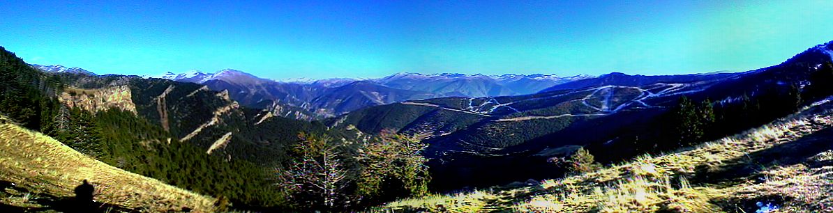
For the past 20 years I have been using fishing poles of various lengths to support wire antennas on “DXpeditions” to my favourite operating site in Andorra, Col de Botella, near the Pal Ski Resort at an altitude of 2200 meters.
When I heard about DF4SA’s massive 18 meter (60 foot) fiberglass pole, I was anxious to try it. The 2007 CQWW Phone Contest provided me with an opportunity to experiment with several different antenna configurations supported by the pole and to do a lot of testing in a couple of days.
The plan was to drive up to the Col on Friday afternoon and spend the entire weekend in my little Romahome Camper. Things got off to a slow start when it snowed on Thursday night, making it impossible to reach my destination. By Saturday afternoon, most of the snow had melted on the road, and I was able to get there.
 There are 2 ways to put the pole up and down. You can stretch it out to full length, anchor the base against a car tire or
other immoveable object, and walk it up, or you can fix the base section to a vertical object (such as the steel poles
marking the edge of the road) and extend the pole section by section, locking the clamps as you go.
There are 2 ways to put the pole up and down. You can stretch it out to full length, anchor the base against a car tire or
other immoveable object, and walk it up, or you can fix the base section to a vertical object (such as the steel poles
marking the edge of the road) and extend the pole section by section, locking the clamps as you go.
Both methods worked fine. I found that it was easier to keep the wires untangled and to make changes if I used the section by section method. Especially when working in the dark in sub-zero temperatures. Just remember not to loosen the clamp on the smallest section, or you will have to tilt the pole to get the top back out again.
 The plan was to put up a one wavelength square loop for 20 meters in the diamond configuration, and a delta loop for 40 meters
with a common feedpoint. In theory, the 20 meter loop would be a 2 wavelength loop on 10 meters and the 40 meter antenna
would be a 3 wavelength antenna on 15 meters, providing 4 bands on one feedline when matched with a 4:1 balun to 52 ohm coax.
The plan was to put up a one wavelength square loop for 20 meters in the diamond configuration, and a delta loop for 40 meters
with a common feedpoint. In theory, the 20 meter loop would be a 2 wavelength loop on 10 meters and the 40 meter antenna
would be a 3 wavelength antenna on 15 meters, providing 4 bands on one feedline when matched with a 4:1 balun to 52 ohm coax.
I put up the 20 meter loop first, using two 4 meter poles provided by Con as spreaders. 18 guage insulated wire was used for the elements. 2 mm nylon cord was used to pull the elements into shape and act as guys in 2 directions.
The location I use is limited in that on one side there is a road, and on the other side there is a precipitous drop off. That means that I can't use guys to support the mast, except in 2 dimensions. The antenna has to be self-supporting.
 It was possible to mount the spreaders 12 meters up and raise the mast, but the slightest wind would cause the top to bend. In a flat field, guys, made with 2mm nylon cord, supporting the mast in 4 directions would solve this problem.
In my situation, it was better to lower the spreader and give up a little height. I opted to make the top of the antenna 13.6 meters high, and ignore the top 3 sections of the mast.
This configuration proved stable and was easy to raise and lower to make length adjustments on the elements to tune the antenna. As expected, once tuned, the SWR was 1:1 in the middle of the 20 meter band and 2:1 in the 10 meter band. Bandwidth was adequate for a phone contest. Turning the antenna showed a strong front-to-side ratio, especially on 10 meters.
 Masonry plugs and small screw eyes are inserted into the ends of the spreaders. The wires run easily through them.
After working a few hundred stations on 20 and 10 meters, I decided to create the 40 meter antenna before it got dark. I measured out 43.4 meters of wire and used the same point, 14 meters high, to support a delta loop. The feed was to the same balun.
As expected, the SWR was perfect on 40 meters and OK on 15. I did some operating on 15 meters, and then operated 20 meters until the band closed. On 20 the SWR was still 1:1 in the center of the band, but the bandwidth was much less with the extra loop in place.
After a pleasant dinner in the camper, and several glasses of red wine, I decided to give 40 a try. This is a pretty casual way to operate a contest. The object is maximum enjoyment, not maximum score.
The SWR on 40 was 1:1 and the radio was putting out full power, but nobody could hear me. It was very frustrating. 60 over 9 Europeans would repeat their CQ when I called. I really don't know why the antenna didn't work. This is what happens when you design antennas off the top of your head instead of using modelling software.
I don't know if it was too much wine or the long day raising and lowering the antenna, but I became very sleepy and not very motivated. I crawled under the duvet and dreamed of being rare DX so everyone would hear me, no matter how weak I was. Oh, I am rare DX. I guess even when you are rare, you still have to radiate some RF to be heard.
Long before dawn, I woke up and decided that I would have to change the antenna. The easiest thing to do would be to cut a simple 40 meter dipole and make an inverted-Vee. With my LED headlamp in place, I ventured into the sub-zero darkness and lowered the mast. It was not difficult at all to remove the two loops and put up a 40 meter dipole. A quick trim at the ends and resonance was found. By 6:15, I was on the air. I worked P40A, PJ2E and V26B in quick succession with one call each. I guess this one works. Amazingly, I was even able to make some contacts on 15 meters before daylight in Andorra.

Spiderbeam Pole supporting a 40 meter Inverted Vee
When 40 meters died out, and the sun was warming the air, I decided it was time to get back on 20 meters. Down came the mast again.
 It occurred to me that it really wasn't necessary to use the fiberglass spreader, and that the diamond shape could be
maintained by pulling the corners out with cord to anchor points on the adjacent roadside poles, about 20 meters away.
It occurred to me that it really wasn't necessary to use the fiberglass spreader, and that the diamond shape could be
maintained by pulling the corners out with cord to anchor points on the adjacent roadside poles, about 20 meters away.
Using the same loop as yesterday, I raised the mast again. The resulting diamond shape was not much different than before. Without the weight of the spreader, it would be easy to raise the top of the loop to at least 15 meters, and probably higher without guy wires in the orthogonal directions.
Without the 40 meter loop in parallel, the bandwidth on 20 was much greater. This was nice. But on 10 meters the SWR was higher than before. Fortunately, my Icom IC-7000 didn't seem to mind and I was able to operate 10 meters anyway. By the end of the afternoon, I had made 486 contacts on this dead band at the bottom of the sunspot cycle running 50 watts to a wire antenna.
Once again, in the late afternoon, I got out the wire cutters and snipped some wires. I made up an 80 meter dipole to use once it got dark.
After dinner, in total darkness, I lowered the mast and replaced the 20 meter loop with the new 80 meter dipole and the 40 meter dipole from this morning. A few times up and down and I was able to achieve resonance on 80 meters and bang off a couple of hundred contacts.
But when I switched to 40 meters, the proximity of the antenna to my rig caused RF feedback to enter the control head and cause it to shut down. My fiberglass camper doesn't provide the faraday shield of a steel automobile.
Oh well, I ventured back into the cold night to take down the 80 meter dipole and leave the 40 meter inverted Vee back where it was this morning. That worked fine, and I was able to make another 100 or so contacts before quitting for the night.
In summary, I was very happy with the Spiderbeam mast. It was easy to assemble and could be raised and lowered with little effort. I must have put it up and down 20 times on the weekend. There are certainly lots of portable or even permanent antennas that could be made from simple verticals to complicated loop arrays using this handy pole.
I have always been curious as to how the resonant frequency of a dipole changes as you reduce the angle at the apex of an inverted-Vee antenna. Having some time on Monday morning to experiment, and with the handy SWR analysis display of the IC-7000, I decided to play with the antenna before bringing it down.
By moving the ends of the antenna, easily done as they were tied to stone weights, I could change the resonant frequency from 6850 KHz to 7150 KHz without adjusting the feed point or the wire length. The sharper the angle, the higher the frequency.
Of course, the pattern changes as well, but it is interesting information, and it means you can tweak the SWR a bit without a lot of trouble when putting up a portable antenna.
| Spiderbeam Mast Section Heights | |
| 1 | 1.7 m |
| 2 | 3.1 m |
| 3 | 4.6 m |
| 4 | 6.1 m |
| 5 | 7.5 m |
| 6 | 9.1 m |
| 7 | 10.6 m |
| 8 | 12.1 m |
| 9 | 13.6 m |
| 10 | 15.1 m |
| 11 | 16.7 m |
| 12 | 18.2 m |