| BenLo Park |
| Back |
| Next |
| Contact |
|
Links: Charles Benton KAP Encyclopedia KAPER Scott Haefner KiteKam RC Flysoft and lots more |
Kite Aerial Photography for the Simple Minded
The camera and shutter control are completely self contained and can be used in any situation where you would like to take a number of photos automatically at a set interval in time. In this case it is for Kite Aerial Photography, but I have used this camera with an RC plane as well. I am sure you will come up with many more interesting applications for this camera. I look forward to hearing how you use this design. The inexpensive LMC555 CMOS Timer IC can be configured as an astable oscillator. That is a fancy way of saying that it can close a switch every few seconds, open it again and repeat until the camera’s memory is full. In this case, at a resolution of 640x480, that is 180 pictures, or 15 minutes of photography. A more sophisticated intelligent shutter control which still requires no external power and only 2 wires to connect to this camera or any camera with similar features can be built using Texas Instruments MSP430 line of low power microprocessors. I have recently constructed a controller for the GoPro HD Hero camera. GoPro HD Hero Controller. As the Mustek Mini 3 camera shutter is a simple switch (not all cameras are), this simple circuit will operate the camera automatically, taking a picture every 5 seconds, from the time it is turned on. It only takes one IC, 3 resistors, and a capacitor to build it. The power is stolen from the shutter circuit of the camera.
The values below will close the shutter switch for half a second every 5 seconds:
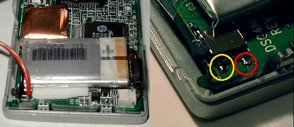
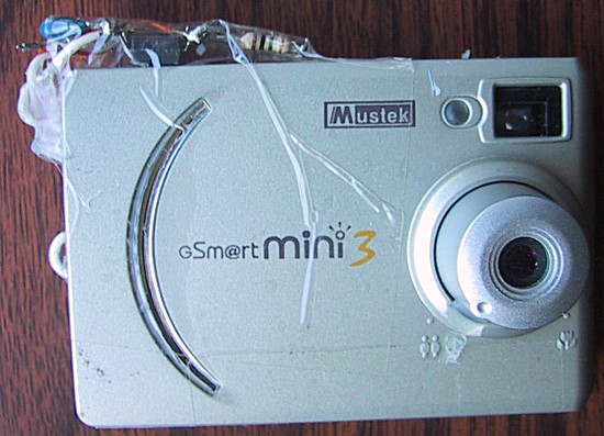
The 555 IC must be the CMOS type as it is being powered by the camera itself. The capacitor should be of a low leakage type, or the actual time will be longer than the calculated value. There is nothing critical about the construction. For minimum simplicity and weight, I used the “dead bug” construction method of flattening the IC and wiring the parts together without a circuit board. The resulting circuit was then be taped to the outside of the camera. Different timing can be arranged by changing the value of R1 or C1. For a 15 second timer, change R1 to 3 Megohms. If you find that the time is shorter or longer than expected due to the capacitor leakage, adjust R1 accordingly. If you want different times, you could use a miniature trimpot in place of the fixed resistor, or build multiple copies of the timer and use a jack and plug arrangement to connect them to the camera. If you change C1, you should adjust the value of R2 as the combination determines the time the shutter switch is closed. Too short a time and a picture will not be taken. Too long a time will waste battery power. Rob Paisley has created a very informative web page with lots of simple circuits using the 555 Timer IC. His Astable Oscillator Calculator will help you choose the correct values for your shutter control. The circuit could also be built with surface mount components and would then fit inside the camera by turning the battery the other direction and placing the new parts over the shutter switch. Connecting the Timer to the Camera The RC Creative Electronics web site shows step by step how to open the Mustek Mini 3 camera and wire a connection to the shutter control. The red wire goes to positive. The black wire goes to the negative connection on the timer circuit.
Hot glue is used to seal the wires coming out of the camera to take any strain off the solder connection. The parts are taped to the top of the camera with transparent shipping tape. The complete camera and timer circuit weighs less than 40 grams (1.4 oz). It’s ugly, but it works great.
I have also dripped a blob of hot glue on the edge of the lens in order to prevent it turning away from the distant setting and ruining the focus of the pictures. It is easy to accidentally turn the lens when setting up the camera and attaching it to the kite string. Operation Turn on the camera as usual. You have 5 seconds to select the mode you wish to use. I usually use the 640x480 mode, which requires pressing the mode switch twice to select the smallest size. I have also used the 1600x1200 size which is the default when the camera is turned on, but only takes 30 pictures. If you take too long getting ready, or the kite doesn't fly as expected, you may wish to delete the first batch of pictures in order to relaunch with empty memory. Just press the delete button twice to select delete all. In a few seconds the timer will activate the shutter and delete the extra photos. Press the mode button as needed and you are ready to go.
The circuit should also work with other miniature cameras such as the Aiptek miniature cameras but I haven't tried it. Please let me know if you experiment with other cameras so I can list them here. The Schieppati switch from RC Creative Electronics is a tiny circuit containing a PIC microprocessor which allows control of the camera via radio control. A similar PIC circuit could be built and programmed to operate the camera with different timings (such as a long delay before the first picture is taken). |
|
The Kite
Frameless Design |
|
The Camera
640x480 to 2048x1536 |
|
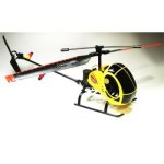
The Helicopter
Ready to fly |