The Button - a WiFi connected push button
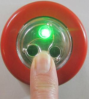 The button is one of those project that is easy to make and useful in more ways than I can count.
The idea is simple. Press the button and a connection is made to a web server which will perform
the desired task. Some ideas:
- Panic Button! Send instant notifications, SMS messages, emails to friends and relatives.
- Doorbell. When the button is pushed, receive a notification on your phone.
- The Doctor is ready. Or anyone else who needs to inform someone when they are ready.
- Booty Call. When you are in need of that special friend with benefits.
- Connect to Pushbullet to send instant notifications or trigger IFTTT actions.
- Connect to Twitter, Instagram, Facebook, Whatsapp, or any other social medium with an API.
- Toggle a light on and off, anywhere in the world.
- Turn on any internet controlled device, wherever it is.
- Turn on anything plugged in to a Kankun Smart Plug
- Check out bttn on Indiegogo for a lot more ideas.
- Check out Flic on Indiegogo for even more ideas.
What is this one used for? When the kettle is boiled and Jane wants to summon me to
afternoon tea, she presses the button. I get a notification on my phone, my tablet, and my chrome browser.
Time for a break.
How much did it cost? The bttn IndieGoGo campaign
offers a similar button for the special price of $99 each. Do it yourself and save more than $95.
Make some for your friends.
Bill of materials:

Choose your favorite color. These buttons are available in many colors.
Build different colored buttons for different applications.
Take it apart. Unscrew the cover from the battery compartment. The insert containing the PCB, button
and LEDs is press fitted into the colored cover. Hold the edge and push the insert out the bottom.

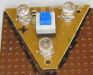 Remove the printed circuit board with the white LEDs and button. Use that board
as a template to cut a piece of perfboard for the new button and the RGB LEDs.
You could use the white LED and existing button if you want a button that does not need to be
held down until the connection completes.
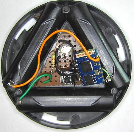 The perfboard holds the RGB LED, the resistor, and the push button.
The method of assembly is not critical.
In this case, only one resistor is used because the software will ensure that only one of the 3 LED
components will be on at a time. 1K gives an adequately bright light. 470 ohms could be used for brighter.
If you are going to combine LEDs with a PWM method for other colors, then it is recommended that
individual resistors be used on each color.
There is room for the tiny ESP-03 board between the switch and the side. If you want to use a larger board with
a PCB antenna, such as
the popular ESP-01,
the plastic can be cut away from one of the battery compartments as we are going to
use only 2 AAA batteries for power.
Three batteries can be used with a voltage regulator to provide a more stable power
supply, but it appears that the ESP8266 will operate fine with 2 alkalyne AAA batteries. It won't work with
NiCd or NiMH batteries as the voltage from 2 batteries would be too low. The voltage from 3 fully charged
cells would be too high without a regulator. I prefer to stick with 2 AAAs and no regulator for this project.
Buy me a beer. Donations to support this web site are gratefully accepted. You can use PayPal, credit card, or bitcoin. No amount is too small.
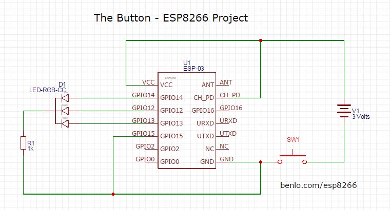
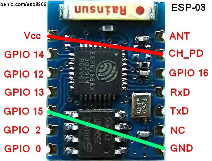 The circuit is quite simple.
The LEDs are driven directly by the GPIO pins, which are capable of driving 12 mA in this mode.
The battery is 3 Volts. That is 2 cells. It is necessary to short out the third cell
compartment so that only 2 cells are used. 3 cells will destroy your ESP8266 chip. Guaranteed.
The CH_PD pin must be held high to enable the chip. Some users recommend a 12K resistor to Vcc instead of a direct
connection. This is only necessary if there is any danger of programming the pin as an output and setting it low.
GPIO 15 must be held low to boot properly to operate the Lua interpreter. Once again, a 12K resistor
could be used.
Programming the ESP-03. Connect the GPIO 0 pin to ground to enable programming the flash memory
with the NodeMCU firmware. Connect the Tx and Rx of the ESP-03 board to the Rx and Tx of your USB serial
adapter. Use the NodeMCU flasher application to program Lua into the chip. Details are
available in the Quick Start Guide.
Installing the Application. Use LuaLoader to install the
Lua program files which can be downloaded from
github.
You are encouraged to extend the
program and upload your own version for others to use.
init.lua is run automatically when power is applied to the chip. The pins for the red, green and blue
LEDs are defined and the GPIOs are initialized. After 1 second delay, the autoconnect.lua script is run.
The LED is red.
autoconnect.lua makes a list of available open access points within range. It then attempts to connect
to the strongest access point available.
As it attempts to connect, the LED flashes red. Once a connection is established, the LED turns blue
and httpget.lua is run.
httpget.lua connects to benlo.com (change to your host) and sends a data message
to a php script containing the identity of this button and other parameter.
The program you downloaded connects to benlo.com/esp8266/test.php. Change the address to your
own host and script before using this program.
If the connection is successful, the LED changes from blue to green. When the connection is disconnected,
the reconnect.lua script is run.
reconnect.lua changes the LED back to red and attempts to connect to the next strongest
available access point if there is one. The process repeats until all of the access points have been tried.
Using the button
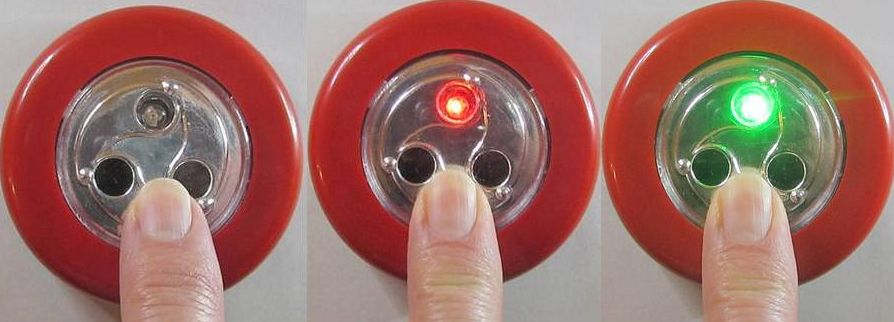
As you might expect, the button only has one button.
Press the button and hold it.
The LED will turn red to indicate that the button has powered up and is searching for open hot spots.
After listing the available hot spots, the LED will begin to flash as the button attempts to connect with them,
starting with the strongest one first.
When a connection has been established, the LED turns blue. The button will attempt to connect to the host
server, benlo.com, by default.
If a connection is established, and the expected response is received, the LED will turn green.
At this point, you can let go of the button.
If you continue to hold the button down, the button will attempt to connect with the next strongest hotspot.
This is not necessary, but may be interesting if the server program is keeping track of what hotspots are
reachable from a given location.
Server Script
What happens after the button has connected to the server depends on what you have programmed
the server to do after a connection. The sample script below sends a pushbullet notification to
a phone and an email to a recipient. The email address could be an
SMS gateway which would send
an SMS message to a phone. Many providers have email addresses which automatically forward to
SMS.
<?php
echo "button received\n";

$msg = "\nThe red button was pushed.\n";

require 'PushBullet.class.php';
$p = new PushBullet('yourOauthToken');
$p->pushNote('yourDeviceToken', 'RED Button', $msg);

mail("fwb@gmail.com","RED Button",$msg,"From: me@gmail.com\r\n");
?>
PushBullet.class is a handy library for using the PushBullet API by PENDOnl. Thank you Joshua, for
making this code available.
What next?
This implementation of the button is a good proof of concept.
A small modification to the code will allow the button to connect with
one or more password protected access points.
Once the button is working
a lot of complex actions can be set up via the host server or other internet of things providers
to add more functionality. Check out IFTTT to see what actions you can tie to your button.
The script can track the hotspot used and the signal strength to determine
where the button is when it was pushed.
On the button end, the RGB LED can respond to whatever data the server sends it back.
Press a button and get an instant response to whether your stock is up or down.
Do you need an umbrella today?
Is someone home?
The analog input on the button can give the battery status
or a sensor for temperature or humidity can be incorporated in the shell.
The ESP-03 board has a connection for an external antenna. A
3cm wire (λ/4) will increase
the range dramatically. Add another 3cm wire to ground and make a dipole.
The source code to get you started is on github. I really look forward to seeing what
you can do with this simple project. Please post your code as a fork, so we can all share.
Open Hotspot finder
 I have been buying my ESP8266 boards from ebay seller, Tom Yuen in Marietta, GA.
I have been satisfied with every board I have received and the delivery times have been extremely fast.
Tom recently added a new ESP8266 Development board with an ESP-12, a 3x AA battery holder, a voltage regulator, an RGB LED, several red LEDs, and a light sensor on the ADC input all on one board. It comes
with a USB to Serial interface or
without one.
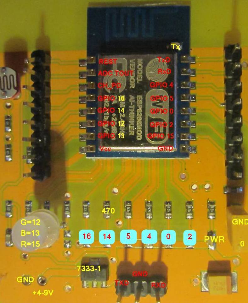 After experimenting for a while, I was able to sort out the various pin connections and identify
which LEDs were associated with which GPIO pins on the attached ESP-12 board.
The board can also be controlled by an open source Android App which is available from the
AI-Thinker web site.
My goal was to create a simple hand held hot spot locator, which would quickly tell me
if I can connect to one of the several WiFi routers around our home from any given
location. If this works, then I can create other IoT gizmos that automatically seek out
the strongest signal and connect to them automatically. My WiFi access points do not
require a password.
In most cases, the use of a device like this to connect to a WiFi hotspot requires the authorization
of the owner of the access point. Please only use this code to access hotspots which you are already
authorized to use.
No connections are needed to the board, other than the usual TXD, RXD and ground for programming.
This board comes with the battery already wired.
When power is applied to the board, the program searches for access points that are in range and
chooses the strongest one that is open and does not require a password to connect. If it finds any open access points
in range, the LED changes from RED to BLUE.
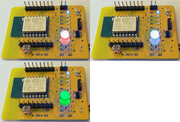 Hotspot finder then attempts to connect to the access point and, once connected, it
sends a query to a php script on a web site.
If the expected response is received, the LED changes from BLUE to GREEN.
If a response is received, but it does not match the expected response, it indicates
that there may be an additional login required, or the access point is not connected to the internet,
and the LED changes to PURPLE.
After 5 seconds, the LED goes off. If power is left on, the finder tries again in
30 seconds.
Experimentation has shown that a connection can be established and verified in less than 3 seconds.
LUA source code on github
Ask Google for the Time
This is an example of how to connect to Google using an ESP8266 running NodeMCU Lua and retrieve just the HEAD information, which happens to include the current time.
It would be possible to do this with NTP, but that would require more coding. The results wouldn't be any more accurate. I am pretty sure Google keeps the time on their servers well synchronized with the actual time.
-- retrieve the current time from Google
-- tested on NodeMCU 0.9.5 build 20150108

conn=net.createConnection(net.TCP, 0)

conn:on("connection",function(conn, payload)
            conn:send("HEAD / HTTP/1.1\r\n"..
                      "Host: google.com\r\n"..
                      "Accept: */*\r\n"..
                      "User-Agent: Mozilla/4.0 (compatible; esp8266 Lua;)"..
                      "\r\n\r\n")
            end)

conn:on("receive", function(conn, payload)
    print('\nRetrieved in '..((tmr.now()-t)/1000)..' milliseconds.')
    print('Google says it is '..string.sub(payload,string.find(payload,"Date: ")
           +6,string.find(payload,"Date: ")+35))
    conn:close()
    end)
t = tmr.now()
conn:connect(80,'google.com')
Right click to download googleTime.lua
The program can be saved to a file, google.lua. Then, dofile("google.lua") will retrieve and print the time. From this location, the normal elapsed time from requesting to printing was under one tenth of a second. Pretty good.

How does it work?
A TCP type connection is created and the event driven functions are assigned to on "connection"
and on "receive". conn:connect(80,'google.com') connects to Google. When the connection is made,
the on "connection" event is fired. At this point, the "HEAD..." message is sent to the server,
causing it to respond with a few lines of information. One of those lines contains the date and
time. The string.sub() function extracts the date and throws away the rest.
Simple scripts like this are easy to enter and test with LuaLoader.
�
ESP8266 Rain Gauge Monitor
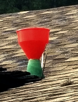 We have had a rain gauge on our roof for more than 25 years. Originally, this
funnel and tipping bucket
style gauge operated an electro-mechanical counter.
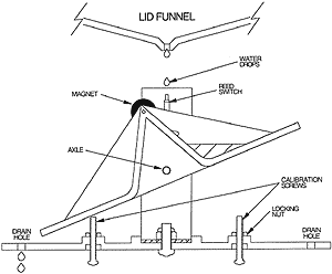
A funnel collects water over a known area and directs it to a tipping mechanism. When the bucket
fills, it tips the see-saw over. The bucket and funnel area can be calibrated to flip at exactly
0.01 inches of rainfall. As the buckets flip, a magnet passes a reed switch, producing a momentary
closure. The original product had a mechanical counter which advanced by 0.01 each time.
In the mid-90s, I interfaced this rain sensor, along with temperature and humidity sensors, to a PIC board which collected the information to an EEPROM along
with temperature and other information.
 The PIC was connected to a modem and would dial up our ISP,
connect and upload the information to my web site by ftp. That worked great until we switched to DSL. By
then, I no longer had a programmer to reprogram the PIC, so the entire project gathered dust in the attic.
The low cost of the ESP8266
and the ease of programming it in Lua has made it possible to
connect everything to the internet with only an hour or two of work. There are 3 running 24/7 at our house
already, and more expected soon. So far, they have proved to be extremely reliable and useful.
For this project, the ESP-03 was used, but as it only needs one GPIO input pin, any of the available
boards will work.
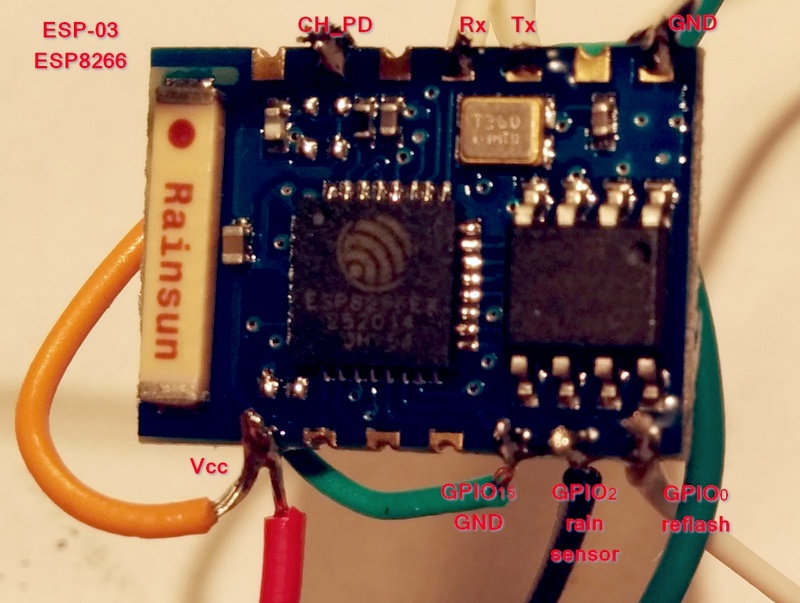
Any GPIO input pin can be used, but beware that if GPIO0 or GPIO2 is held low during a power reset,
the ESP8266 enters reflash mode instead of running the program.
 An LTV-817 optoisolator keeps the ESP board safe from harm. In this case, the electromechanical counter is still in the circuit, so there are considerable inductive surges to worry about. In fact, a reverse diode was connected across the LED of the optoisolator to protect it from excessive reverse voltage.
Every 0.01 inches of rain, the bucket flips and the reed switch closes for a few milliseconds.
When this occurs, the counter and the LED in the optoisolator are energized.
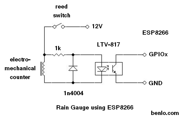
The ESP8266 is programmed to fire an interrupt when the GPIO input transitions from
high to low. The interrupt calls the counter function below.
In the real world, switches bounce, resulting in multiple pulses for a single transition.
The delay timer insures that any further pulses that occur within 250 milliseconds of the first one will be ignored.
-- Count pulses on GPIO2

count = 0
delay = 0
gpio.mode(9,gpio.INT)

function counter(level)
   x = tmr.now()
   if x > delay then
      delay = tmr.now()+250000
      count = count + 1
      print(count)
      end
   end
gpio.trig(9, "down",counter)
Every tenth of an inch, and every hour if there was no rainfall, the processor connects to this web
site and uploads the total rainfall count to a php script which saves the data to a file.
The script can be used to update a weather page, send email alerts, SMS messages, or
PushBullet phone and browser notifications.
�
ESP8266 Well Power Monitor
I needed a simple way to monitor the pump on our well.
Once in a while, something goes wrong and it fails to run. We don't notice until the holding tank empties and there is no water. Then we have to go figure out what happened - breaker problem, switch problem, power bill not paid, etc...
Other times, like last month, the pump remains on 24/7 and the water overflows the tank until someone notices. It took 35 days at 2KW before anyone noticed. $400 electric bill!!!!! The well and tank are not visible or even easily accessible from the house.
Seems like a good application for the esp8266.
A 3.3 volt wallwart is connected in parallel with the pump relay to power the esp8266 when the pump is on. When the pump is off, so is the esp8266 board. The hardware couldn't be any simpler.
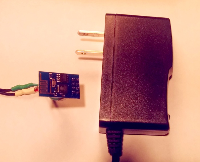
When power is on, the monitor connects to a nearby WiFi access point and pings a php script on my webserver. The PHP script logs the times and sends an email alert if the pump hasn't run for more than 24 hours, or if it has run for more than 2 hours straight. Normal operation is an hour a day.
Inspired by Mark and Xavi's How to use ESP8266 ESP-01 as a SENSOR web client post, I decided to use Lua for this quick job.
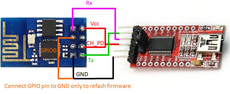
An ESP8266 flasher program for Windows is available at ESP8266_flasher.
The LUA Firmware nodemcu_512k.bin came from nodemcu's github repository. Version 0.9.2 was used for this project.
To burn the new firmware use a
3.3 volt FTDI USB to serial adapter .
Connect the GPIO0 pin to GROUND for programming.
After burning, the GPIO0 pin should be disconnected from ground in order to reboot in normal mode.
Connect to the ESP8266 using your favorite terminal program (PuTTy,SimpleTerm) to work with Lua directly on the ESP8266 board.
On the esp8266 set up the AP SSID and password using Lua commands.
wifi.setmode(wifi.STATION)

wifi.sta.config('SSID','password')
Check with print(wifi.sta.getip()).
This is conveniently stored permanently in flash memory!
Below is the method for feeding code to the ESP8266 over a serial terminal at the Lua prompt. This is how to upload code if you are using a dumb terminal.
LuaLoader simplifies that a lot. The code below was also my first
attempt. A much better internet connection function is
httpget.lua on my github.
file.remove('benlo.lua')
file.open('benlo.lua','w')
file.writeline([[conn=net.createConnection(net.TCP, 0) ]])
file.writeline([[conn:on("receive", function(conn, payload) print(payload) end) ]])
file.writeline([[conn:connect(80,'se.rv.er.ip') ]])
file.writeline([[conn:send("GET /yourscript.php HTTP/1.1\r\n") ]])
file.writeline([[conn:send("Host: yourserver.com\r\n") ]])
file.writeline([[conn:send("Accept: */*\r\n") ]])
file.writeline([[conn:send("User-Agent: Mozilla/4.0 (compatible; esp8266 Lua; Windows NT 5.1)\r\n") ]])
file.writeline([[conn:send("\r\n") ]])
file.writeline([[tmr.alarm(30000, 0, function() dofile('benlo.lua') end )]])
file.close()
As you can see, this script just connects to the web server once every 30 seconds when the power is present.
The output from the webserver script gets sent to the UART if the computer is connected. Otherwise, it just blinks the blue LED on the board, giving visual feedback of successful operation.
To start on power up, init.lua waits 10 seconds for the connection to the WiFi AP and starts benlo.lua
file.remove('init.lua')
file.open('init.lua','w')
file.writeline([[print('Peter LUA module 0.1')]])
file.writeline([[tmr.alarm(10000, 0, function() dofile('benlo.lua') end )]])
file.close()
Notes
The benlo.lua code could just be incorporated into init.lua, but I like the idea of keeping it separate.
DNS was not working in the NodeMCU code at the time this was written, so the IP address was manually entered.
User-Agent: leaving out this line or using esp8266 as the user-agent caused the Apache server
to return a 500 error when accessing PHP. HTML pages were returned normally. Took me a while to track that one down!
When feeding serial input to the Lua prompt, a 200 mSec delay after each line was used.
Update after one week. The ESP-01 board proved to be extremely reliable.
The pump is located far from the nearest access point and neither my Nexus 5 phone or Nexus 7
tablet would connect from that location. (Wifi Analyzer reports -85db). I didn't expect the ESP8266 to work, but decided to leave
it connected and see what happened. It connected perfectly 768 times out of 768 attempts!
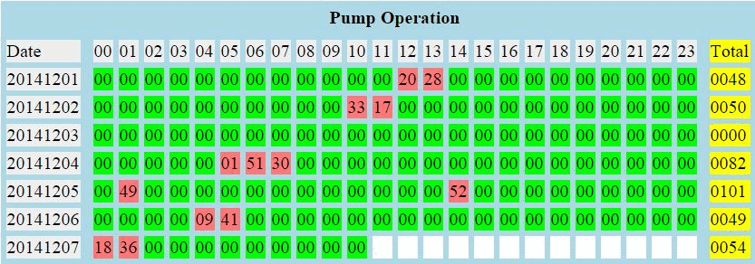
A cron job sends the chart as a daily email. If the pump runs longer than 2 hours, or
doesn't run for more than 24 hours, it sends an alert notification to my phone and to
the other neighbours sharing the well.
Links:
Mark and Xavi's Post on using Lua
NodeMCU Lua Development
ESP8266 Forum with Lua Threads
Lua Language
Windows SDK Setup
Peter Scargill's Useful Blog
 The button is one of those project that is easy to make and useful in more ways than I can count.
The idea is simple. Press the button and a connection is made to a web server which will perform
the desired task. Some ideas:


 Remove the printed circuit board with the white LEDs and button. Use that board
as a template to cut a piece of perfboard for the new button and the RGB LEDs.
You could use the white LED and existing button if you want a button that does not need to be
held down until the connection completes.
 The perfboard holds the RGB LED, the resistor, and the push button.
The method of assembly is not critical.
In this case, only one resistor is used because the software will ensure that only one of the 3 LED
components will be on at a time. 1K gives an adequately bright light. 470 ohms could be used for brighter.
If you are going to combine LEDs with a PWM method for other colors, then it is recommended that
individual resistors be used on each color.
 The circuit is quite simple.
The LEDs are driven directly by the GPIO pins, which are capable of driving 12 mA in this mode.
The battery is 3 Volts. That is 2 cells. It is necessary to short out the third cell
compartment so that only 2 cells are used. 3 cells will destroy your ESP8266 chip. Guaranteed.


 I have been buying my ESP8266 boards from ebay seller,
 Hotspot finder then attempts to connect to the access point and, once connected, it
sends a query to a php script on a web site.
If the expected response is received, the LED changes from BLUE to GREEN.

 We have had a rain gauge on our roof for more than 25 years. Originally, this
 The PIC was connected to a modem and would dial up our ISP,
connect and upload the information to my web site by ftp. That worked great until we switched to DSL. By
then, I no longer had a programmer to reprogram the PIC, so the entire project gathered dust in the attic.


