DIY GoPro HD Camera Controller
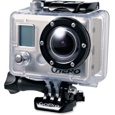
The GoPro HD Hero Camera is an amazing little unit that comes with a variety of mounting accessories making it ideal for attaching to my helmet when I am paragliding, or to my car when I am driving. I was lucky to get one for Christmas and I am making good use of it.
It can be used to take HD videos or 5 Megapixel still images. Automatic time lapse mode will take a photo every 1, 2, 5, 10, 30 or 60 seconds.
You would think I would be satisfied...
I guess some hackers are never satisfied.
Intelligent Camera Control

The first thing I noticed was that the time lapse mode did not turn off the camera between shots. Instead of going to sleep, it remained on, depleting the battery in a few hours, even when there is lots of room left on the 32GB SD card.
Then, there was the possibility of triggering the snaps with a motion detector. Or setting up time-lapse photos that are only taken during the day, controlled by a photocell. Or controlling the camera remotely by radio, or even cellphone. Or taking photos at particular times over a period of weeks. There are just so many options available once you can control it with your own custom programmed microprocessor.

The GoPro HD Hero Bus
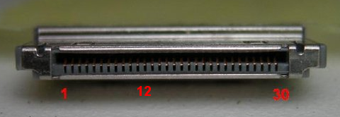
Pin 1 is at the bottom of the camera. Note that some connectors which fit are numbered in the opposite direction - do not rely on the numbers on your connector.
There is a great user forum following this camera, and gopropit has done some work deciphering the pinouts. This was a big head start that allowed me to design and build a controller in just a few hours.
Shorting pin 12 to ground is identical to pressing the PWR/MODE button on the front of the camera. GoPro has provided an option called One Button Mode. In one button mode, if you turn on the camera, it will immediately take a photo†, or begin a sequence of photos, or start recording a video, depending on the settings that were saved before turning the camera off. One button mode means that a simple controller can do amazing things with only two wires.
A male connector which fits is the DD1P030MA1, used by Sandisk, Creative Zen and others. They are available from the usual suppliers such as Mouser and Digikey and in small quantities from Cam-Do.com.

Texas Instruments MSP430

The MSP430 microprocessor platform of ultra-low power 16-bit RISC mixed-signal microcontrollers from TI provides the ultimate solution for a wide range of low power and portable applications. Even more important, complete development systems for small projects are available for as little as $4.30.
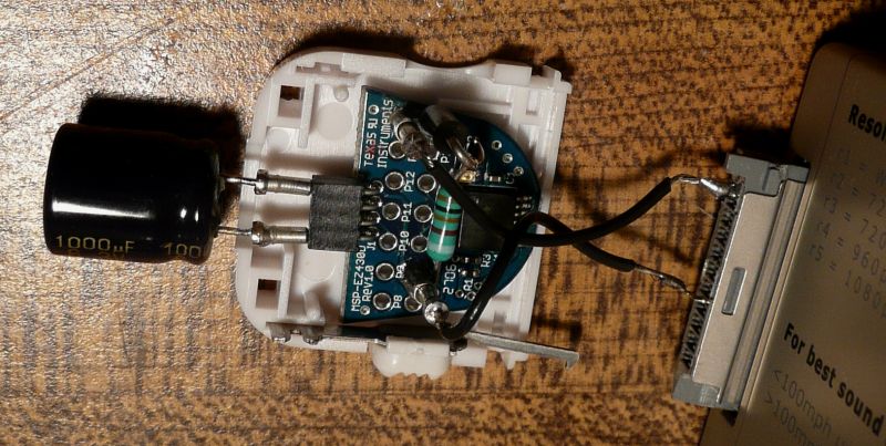
The EZ430 USB stick ($20) and tiny F2012 project board (3 for $10) would be just perfect for this application. In sleep mode it uses almost no power at all. It has outputs which can be used to control the camera with no additional components. It has both analog and digital inputs which will be available for future projects. The chip can be configured with the USB dongle for any number of custom setups. The board itself is small enough to fit inside the connector on the back of the camera.
The Idea
A simple controller that plugs into the bus connector on the back of the camera and takes time-lapse images every few minutes. After taking a picture, the camera is turned off until it is woken up to take another photo. Power is provided by the camera. A simple two wire approach is used, similar to the LMC555 based shutter control used in my Kite Aerial Photography project a few years ago.
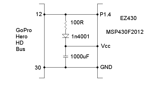
Power is obtained directly from the PWR/MODE button pin on the bus. This provides 3.3 volts at up to 2 mA (determined by measuring the current when shorting the pin to ground). The MSP430 doesn't require nearly that much power. The only problem is that when the pin is grounded to take a picture, there won't be any power for the microprocessor. That was solved with a capacitor, which is charged by the camera while waiting for the next picture taking cycle.
The values are not critical. The capacitor needs to be low leakage. Much smaller ones are available than the one I had in my junk box, which is rather old technology. I used the MSP430F2012 because I had a few spare ones lying around. Any of the MSP430 processors could be used by recompiling the program and making appropriate changes to the I/O and timing.
Donations to support my time and effort and contributions toward the hosting and bandwidth for the web site are gratefully accepted. You can use PayPal or a credit card. No amount is too small.
If you are not handy with electronic projects, you can now buy an assembled and tested controller board configured as a Time Lapse controller with an isolated input for motion detectors or other triggering devices.
The Code
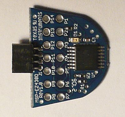
The program only has to do a few things. After initializing the output and setting up the watchdog timer to interrupt every 256 mSec, it goes to sleep.
On interrupt, it decides what to do next which depends on where it is in the picture taking cycle. A cycle consists of: Turn on the camera with a 250 mSec low pulse. Wait 3 seconds for the image capture. Turn off the camera with a 3 second low pulse. Flash the LED to show things are working. Wait until it is time to do it all again.
Download GoProController.c
The code was compiled with the free version of the IAR Embedded Workbench available from Texas Instruments.
Testing
A test unit was assembled and plugged into the camera. It began working immediately.
Single photos were snapped every minute for over a day. It appears that it will take 1.500 to 2,000 photos on a charge. It should not matter if that is one a minute for a day and a half, or one an hour for several months. For maximum efficiency, turn off the LCD, LED and beeper and operate the camera in stealth mode to reduce power consumption.
Remote Control
An RF remote control for the camera can be interfaced with the same hardware and some changes to the software. I used a $4.00 luggage locator picked up on eBay to create an RF wireless remote control.
On the Drawing Board
This is basically a proof of concept design. I have plans...
Real Time Clock
As tested, the internal R/C oscillator was used for the clock. The MSP430 can be configured to use a 32768 kHz crystal for real-time clock accuracy. That would allow the setting of a date and time for turn-on and very accurate timing between shots if required. Only minor adjustments to the code would be necessary.
Timer Interface
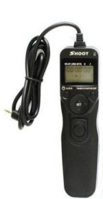
Inexpensive remote control timers (intervalometers) are available for many cameras on eBay for under $20.
It is possible to interface one of these timers to the GoPro using the MSP430 controller. The Cam-Do Controller Board can be used to interface an intervalometer to the GoPro camera.
The timer could also be interfaced with the RF remote control so that it would be possible to control the camera wirelessly, allowing full timer operation of the camera while it is protected by the waterproof housing.
Motion Detector
A small motion detector can be connected to the processor and used to trigger photos or video. The processor could be programmed to shoot several minutes of HD video each time the motion detector is triggered. This would be useful for shooting wildlife or as a security camera.
The motion detector could be wired directly to the processor or interfaced as an RF remote control allowing more flexibility in placing the motion detector and maintaining the integrity of the waterproof camera.
Option Selection
The port connected to the camera can be configured for input or output so it can be programmed to read the state of the PWR/MODE button. Pressing the button in various ways could be used to select among a number of pre-programmed configurations. An LED flashing sequence can be used toconfirm the settings. This saves the need for adding push buttons to the processor board and allows for control without opening the case.
LCD Display
A small LCD display could be added to the processor board and used to program the real time clock in order to set up scheduled photos or videos or for the selection of different pre-programmed options.
Battery State
The camera battery voltage can be read by the A/D converter on the chip. It is possible to change the shooting strategy if the battery is getting low or raise an alarm that the battery needs replacing.
More Ideas?
With both digital and analog signal inputs available to control the taking of photographs or starting and stopping video recording, there are options available that are only limited by your imagination.
I will be proceeding with some of these ideas soon. Your input and feedback would help me decide which designs to work on and what features would make them more useful to you. If there is demand, we could arrange for the manufacture of these intelligent controllers for sale at a reasonable price. Please let me know if you would be interested in such a product. If you need a custom soluton, let's talk.
Disclaimer
Plugging home made devices into your GoPro entails certain risks. The author assumes no liability for any damage which might occur to your camera or any warranty that these instructions will work for you.


