GoPro HD Wireless Remote Control
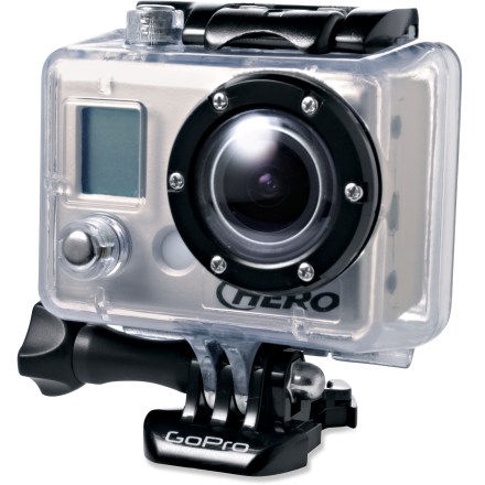
This is an extension of my project to interface the TI MSP430 with the GoPro HD Hero camera to add new functionality.
The previous project was a Time Lapse Controller, which captured photos on a slow cycle and turned off the camera to save battery life between photos.
Using the same hardware, this project shows how to interface an inexpensive remote control receiver to take photos or videos at the press of a button.

Make your own Wireless RF Remote
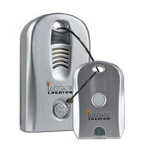
There are lots of remote control transmitters and receivers available on eBay at Amazon and probably in your local discount store.
The circuit shown here is very flexible and will work with almost all of them.
When the button on the remote control is pressed, the baggage locator will beep and the LED will flash. In the particular unit I used, the voltage on the LED is about 3 volts when it is on. This is perfectly compatible with the input to the MSP430 when it is powered by the camera.
When the microcontroller detects a pulse on the input pin, it proceeds to turn on the camera by briefly shorting pin 12 of the bus connector to ground. The camera can be set up to take one or more photos, or to begin recording a video.
The length of time the camera remains on is determined by the software setting TIME_ON. Define this value as 3 if you wish to take a single photo. If you wish to take a sequence of photos, set the camera up in PES mode with the desired rate and leave the camera turned on for the desired length of time. If you wish to take a video, set the camera up in F mode. When the camera is turned on by the controller it will begin to record. When it is turned off, the recording will end.
Texas Instruments MSP430

This project uses one of the MSP430 microprocessors, ultra-low power 16-bit RISC mixed-signal microcontrollers from Texas Instruments. Complete development systems for small projects are available from TI for as little as $4.30.
The EZ430 USB stick ($20) and tiny F2012 project board (3 for $10) are what I used. In sleep mode it uses almost no power at all. It has outputs which can be used to control the camera with no additional components. It has both analog and digital inputs which will be available for future projects. The chip can be configured with the USB dongle for any number of custom setups. The board itself is small enough to fit inside the connector on the back of the camera.
The Hardware
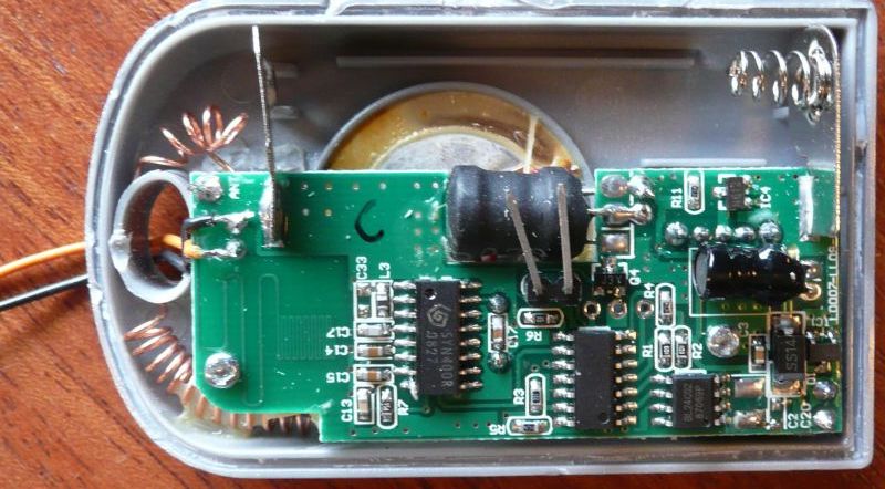 The ETA Luggage Locator I used has an LED that glows when the control signal is received.
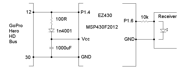
The input pin p1.6 is connected to the positive side of the LED through a resistor. The negative side of the LED is connected to ground.
The luggage locator receiver has its own AAA battery.
If you are interfacing a remote control with a 5 volt signal, use a resistor divider to lower the voltage to 2.5V to 3.0V.
Power is obtained directly from the PWR/MODE button pin on the bus. This provides 3.3 volts at up to 2 mA (determined by measuring the current when shorting the pin to ground). The MSP430 doesn't require nearly that much power. A capacitor, charged by the camera while waiting, powers the microprocessor when the P1.4 output shorts pin 12 to ground.
The values are not critical. The capacitor needs to be low leakage. Much smaller ones are available than the one I had in my junk box, which is rather old technology. I used the MSP430F2012 because I had a few spare ones lying around. Any of the MSP430 processors could be used by recompiling the program and making appropriate changes to the I/O and timing.
If accurate timing is required, it is only necessary to add a 32768 Hz crystal to the board and modify the software to use the crystal controlled clock instead of the internal R/C clock.
Donations to support my time and effort and contributions toward the hosting and bandwidth for the web site are gratefully accepted. You can use PayPal or a credit card. No amount is too small.
The Code
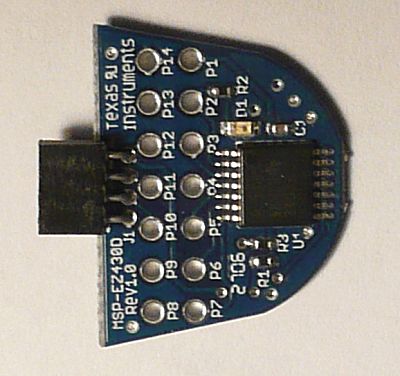
The program begins by initializing the input and output ports, sets up the watchdog timer to interrupt every quarter second, and then goes to sleep.
When the input on pin 1.6 transitions from low to high, an interrupt is generated and the Port 1 interrupt service routine takes care of it. The state variable is changed to STARTING and the output is lowered, effectively pressing the PWR/MODE button of the camera.
Every quarter second the watchdog timer generates an interrupt. The action taken depends on the value of the state variable. When the state = WAITING, nothing is done except to advance the tick count.
When the state is STARTING, if a full 250 mSec or more has passed, the P1.4 output is raised (releasing the PWR/MODE button). The state is changed to WAITING_CAMERA. This is the time allowed to take one or more pictures or to record video. This time must also be longer than the time the remote receiver flashes its LED.
When the second counter (time) is greater than the TIME_OFF time, the output is again lowered (pressing the PWR/MODE button) and the state is changed to STOPPING.
After 3 seconds, the camera recognizes that the PWR/MODE button is being held down and powers down. The controller returns to the WAITING state and waits for another signal from the remote control.
Download RFremote.c
The code was compiled with the free version of the IAR Embedded Workbench available from Texas Instruments.
The Prototype
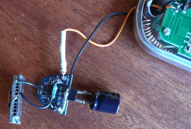
The same hardware was used for the RF wireless remote control as was used for the timer remote control. Only the software needs to be changed depending on the desired functionality.
The prototype worked perfectly. The range was reliable at 25 to 30 feet and worked sometimes at up to 100 feet. Playing with the antennas on the transmitter and receiver would make it more reliable at longer distances.
Long range remote controls with multiple outputs and a range of up to 4000 meters are available from the BATECH store on eBay for very reasonable prices.
This particular remote receiver turned out to be just a hair too large to fit in the expanded back that GoPro provides with the LCD display and extended battery. Other similar devices, such as the key locators available on eBay are smaller and should fit. Stay tuned for an update.
A custom receiver could also be easily built to fit inside the case along with the microcontroller. The luggage locator uses the SYN400R receiver IC, which runs off 3 volts and appears very easy to interface.
A male connector which fits the GoPro camera is the DD1P030MA1, used by Sandisk, Creative Zen and others. They are available from the usual suppliers such as Mouser and Digikey and in small quantities from Cam-Do.com.

Disclaimer
Plugging home made devices into your GoPro entails certain risks. The author assumes no liability for any damage which might occur to your camera or any warranty that these instructions will work for you.

